Microscope:Main
iMAGING prototype is a novel device to detect automatically malaria parasites in thick blood smear samples by digital imaging techniques. It was designed mainly for malaria-endemic countries. The iMAGING prototype is based on the detection of malaria parasites by Artificial Intelligence techniques with Convolutional Neural Networks (CNNs) algorithms. A smartphone device is used to integrate all the mentioned technology in an Android application, control electronic parts/devices, and capture microscopic images by microscope lenses.
The diagnostic tool has been designed to be for Universal use and adaptable for most microscopes, is cheap and affordable, automatically moves the slide and auto-focus the sample, does not require an internet connection, and has robustly trained CNNs to detect malaria parasites in digital images.
This novel diagnosis system is mainly based on 3D printed pieces, electronic parts (step-by-step motors, cables, Arduino controllers, etc), a smartphone, an Android software application, computer software (GLI software, image recognition), and a clinical requirements protocol.
3D Models[edit]
The models are designed by Tinkercad 3D software to transform standard microscopes into automatic slide photo capture systems with auto-focus adjustment. The AutoDesk Tinkercad is a free 3D drawing and was used to design the 3D adaptable models.
Ender 3 PRO printer with CURA 5.1 slicing software has been used in this project to build the designed pieces. The filament is Polylactic Acid (PLA), an easy-to-use, low-cost, biodegradable, and recyclable material.
In Figure 1, the main parts of the slide movement that should be placed on the stage parts of the microscope are shown. Removing the current stage clip is necessary to add the new 3D parts. As an additional complement, we need: 2 metal bars of 2.8mm x 86mm and a spring of 4.6mm x 15mm, as track materials to facilitate the movement of the sample by means of the motors.
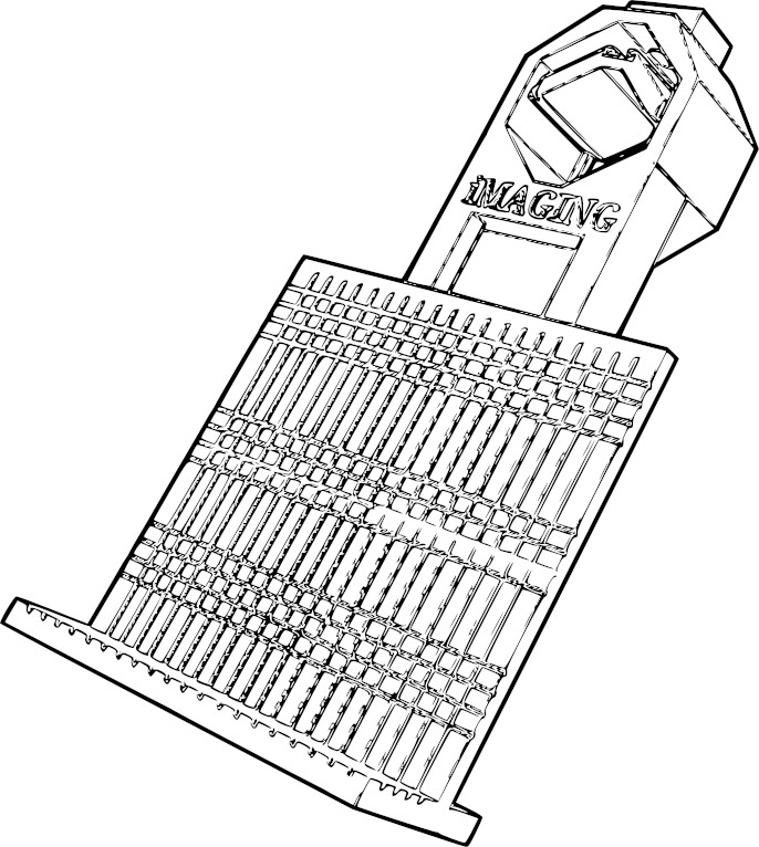
A universal adapter has been developed to attach a mobile device to allow to capture digital images on a common optical microscope. As additional elements, 2 screws with nuts of 6mm x 40mm and 6mm x 60mm were needed to hold the adapter on the microscope (Fig 2).
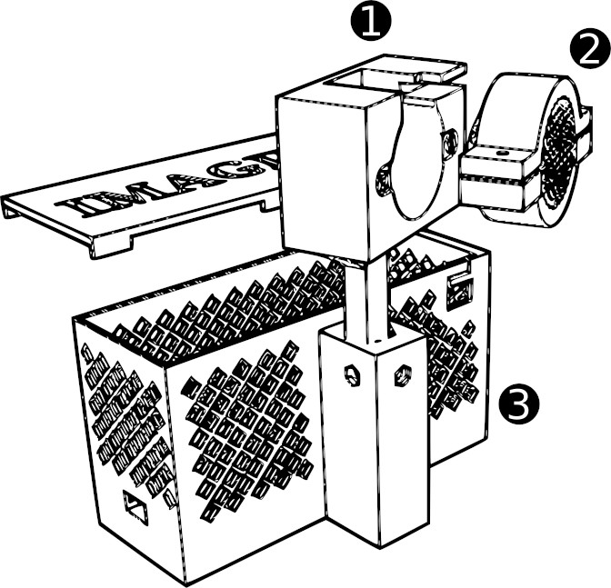
Figure 3 represents the electronic cage of the Imaging device, in which Arduino controllers and step-by-step motor controllers are stored (3). Adapted pieces are built to automatically move the Z axis of the sample and auto-focus the preparation. Pieces (1 and 2 - Figure 3) are attached to the micrometric microscope wheel, and by step-by-step motor movements and a Laplacian Variance algorithm, the sample is automatically focused. The smartphone camera is able to capture focused images by auto-focus algorithm. Captured images are subsequently analyzed by CNN algorithms for object detection.
Assembly and installation procedure[edit]
Before the Imaging prototype installation, Mobile App for Android software must be installed Here we represent the main pieces of the Imaging prototype. These representations would be used as a reference for assembly and installation procedures.
- The kit will be pre-assembled with all the electronics. To install the microscope, simply check the items and follow the steps below.
- Materials and pieces
| Description | Amount |
|---|---|
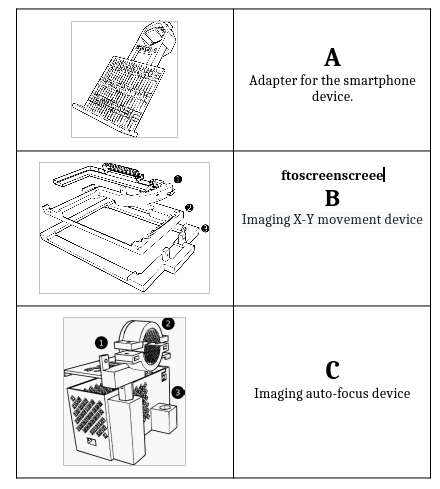
| Imaging adapter for the smartphone device | 1 |
| Imaging X-Y movement device | 1 |
| Imaging auto-focus device | 1 |
| Conventional microscope | 1 |
| Smartphone | 1 |
| Computer (optional) | 1 |
| Imaging Tweezers | 2 |
| USB cable | 1 |
| Imaging Tweezers | 1 |
| Micro-USB cable type B [1m] | 1 |
- Steps
1- Check that the microscope is in optimal condition to perform a diagnosis (light, movements, lenses, etc).
2- Attach the Imaging auto-focus device (C) to the micro-metric wheel of the microscope. Adapt it (part 2) correctly with the exact diameter measure to avoid possible focus issues.
3- Remove the microscope plate stage tweezers.
4- Attach the Imaging X-Y movement device (B) to the microscope plate with Imaging tweezers. It is crucial not to interfere with light or plate movement.
5- Attach the adapter for a smartphone (A) to any ocular lens. Fix it correctly and check if the smartphone device camera captures images correctly through microscope lenses.
6- Connect the USB type B cable from the Imaging auto-focus device (C-3) to the USB port of the computer/energy supply (5V). Check that the green/red LED light of the Arduino is on.
7- Insert the thick blood smear sample on the microscope plate and fix it with the Imaging X-Y movement device (B-1). Put a drop of immersion oil and mainly focus the sample with the 100x ocular lens. Immersion oil must be in direct contact with the sample.


